
Computational Fluid Dynamics (CFD)
Computational Fluid Dynamic
Specialized CFD & Microclimate Simulation Services (PHOENICS)
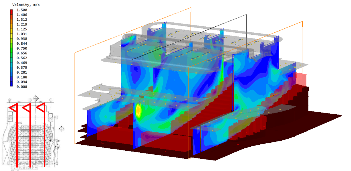
We utilize PHOENICS, a world-renowned, general-purpose Computational Fluid Dynamics (CFD) software engine to analyze complex environmental conditions. To model thermal environments and critical safety parameters in mission-critical facilities and high-occupancy venues.
Our engineering capabilities focus intensely on Data Halls / Mission Critical Data Centres and Large-Scale Auditoriums / Theatres, Outdoor environment flow direction / circulation condition, etc.
We execute a highly structured, data-driven simulation workflow to capture local airflow complexities, eliminate thermal blind spots, and validate performance-based designs.
CFD / PHOENICS
From design inputs to engineering insight
Choose a stage to see the corresponding simulation and explanation.
01 / PHOENICS
Design parameters & boundary conditions
Build the model around the actual geometry, heat loads and ventilation arrangement.
Technical details
Precise server rack arrangements, IT heat dissipation loads (kW per rack), raised underfloor plenums, perforated tile opening ratios, CRAC/CRAH airflow supply curves and ventilation wall arrangements.
Structural geometry, stepped seating, occupant metabolic heat loads, and overhead or underfloor displacement ventilation grille arrangements.
Surface roughness, structural thermal properties, jet flow angles, heat energy inputs and outputs, and buoyancy constraints, using the CAD / Revit import interfaces described in the supplied service brief.
02 / PHOENICS
Steady-state equilibrium modelling
Analyse how airflow and temperature settle under sustained operating conditions.
Technical details
Numerical iterations solve the equations for mass, momentum and heat transfer together.
Steady-state fluid and thermal modelling examines how temperatures stabilise at maximum operating capacity and how continuous thermal loads interact with mechanical extraction.
Assess airflow redirection, local hot spots and temperature increases under disrupted system conditions, such as partial cooling unit failure, recirculation or airflow short-circuiting.
03 / PHOENICS
Visualised results & interpretation
Turn simulation outputs into clear visual evidence and actionable engineering advice.
Technical details
Convert numerical simulation outputs into interpretable visual results.
2D and 3D velocity vectors, pressure gradient fields and multi-slice temperature contour profiles.
An interpretation report translates the results into engineering recommendations and assesses environmental variables against the applicable design criteria and relevant standards.